What is holiday testing, and when is it suitable?
Holiday testing uses electrical equipment to locate discontinuities in a suitable coating system. For marine steel, begin by confirming that the coating portion being tested is electrically non-conductive and that the substrate, return path, film condition and approved procedure support the selected method. A detector alarm requires investigation; a quiet detector alone does not demonstrate that the whole coating system meets its specification.
This guide helps shipyard QA teams, tank-lining inspectors and contractors plan method selection and retain a traceable repair/retest record. It provides no universal test voltage, coating-thickness cutoff or permission to test every marine coating.
Establish the applicable system and standard
The ISO 29601:2026 public catalog lists edition 2, published in April 2026, with a corrected version dated September 2026. The previous 2011 edition is withdrawn. Its scope concerns protective paint on steel or other metals and limits the procedures to electrically non-conductive portions of the system. Equipment choice depends on dry-film thickness.
Identify the edition adopted by the project and resolve any outdated references with the responsible technical authority. The public catalog is not the full procedure. Obtain the adopted standard, current instrument instructions and coating manufacturer's requirements before specifying the test.
ISO describes the methods primarily for new coatings and notes additional considerations for coatings exposed in service, where substances may have penetrated the film. Record service history rather than treating an aged lining exactly like a newly applied one. Conductive coatings, uncertain layer build-up or a substrate outside the adopted method's scope require a separate suitability decision.
Compare wet-sponge and high-voltage approaches
DeFelsko's equipment overview distinguishes low-voltage wet-sponge detection and high-voltage holiday detection. Both require an appropriate electrical path for the intended inspection. The comparison below is a selection aid, not an operating procedure or a list of approved JD settings.
| Approach | Decision-level description | Questions to resolve before selection |
|---|---|---|
| Low-voltage wet sponge | Uses a wetted sponge electrode in the inspection circuit | Does the specified method cover the film thickness and system? Are the wetting medium and surface condition permitted? |
| High voltage | Uses an energized electrode; equipment may provide pulsed or continuous DC | Is the exact equipment/mode suitable? What voltage, electrode and verification requirements are approved? |
| Neither method yet justified | Applicability, film condition or instructions remain unresolved | Which technical review or different inspection method is required before work proceeds? |
Do not choose a method solely because a detector is available on site. Match the specified inspection to the actual coating build-up, measured thickness evidence, substrate and equipment instructions. Marketing thickness ranges do not establish a universal boundary between methods.
Confirm readiness before scanning the coating
Use the following as an editorial planning checklist alongside the approved inspection and test plan. It does not authorize instrument operation.
| Readiness item | Evidence to have available | Hold the decision when |
|---|---|---|
| System identity and applicability | Exact products/layers, substrate, electrical suitability and service history | Conductivity, substrate or layer arrangement is uncertain |
| Film readiness | Product-specific cure evidence, condition assessment and thickness map with units | Required cure or condition evidence is missing |
| Method and settings | Adopted procedure/revision, equipment model/mode and approved voltage basis | Documents conflict or settings lack an approved basis |
| Instrument and circuit | Required calibration/verification evidence, operational check and return-path arrangement | Checks are incomplete or the circuit has not been established as required |
| Coverage and responsibility | Area map, access plan, scanning requirements and designated inspector/release authority | The proposed record cannot show which areas were inspected |
| Site controls | Competent operator, relevant equipment instructions and site authorization | Operating or access conditions do not meet the approved arrangements |
For example, the linked PosiTest HHD instruction manual treats grounding, operational checks, voltage and sensitivity as separate matters. It also gives model-specific electrical safety instructions. Follow the complete manual for the actual instrument; this checklist does not replace those instructions or the site's controls for energized work and tank access.
Keep calibration evidence distinct from an operational check. Record the checks required by the adopted procedure, their outcome and any instrument or setup changes. A calibration document by itself does not describe today's test coverage or circuit condition.
Use an approved voltage basis
DeFelsko's voltage-selection guidance explains the need to detect defects without damaging the film. Obtain the setting from the applicable standard and coating manufacturer's approved instructions. Do not reuse a remembered voltage-per-thickness rule across different systems.
Record the actual thickness evidence and units used to establish the setting, the method/edition and the approved voltage in V or kV. Where a device calculator is used, confirm that its selected standard, edition, units and thickness input match the approved procedure. Do not assume a menu label automatically implements a newly corrected standard.
If the documents disagree, stop the setting decision and seek written resolution. Increasing voltage simply to produce an alarm is not a defensible substitute for that review. This article provides no numerical voltage calculation or recommended setting.
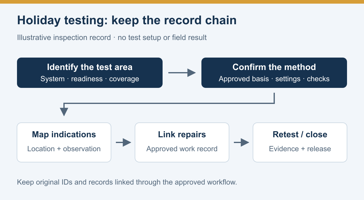
Map indications, repairs and retests
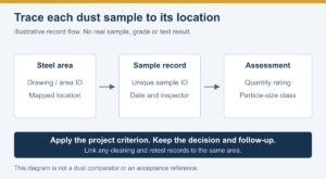
Agree a location convention before inspection: for example, the project's existing compartment, plate, grid or weld identifiers. Choose a system that another inspector can relocate. Avoid a free-standing count such as “three defects” without positions and work references.
The blank structure below is a suggested register, not measured project data. Add the fields required by the contract, instrument instructions and repair procedure.
| Record group | Information to enter |
|---|---|
| Inspection scope | Vessel/structure, area and drawing/grid references, tested boundaries and any inaccessible areas |
| Coating and readiness | Product/system, layer build-up, application/cure evidence, thickness-report ID and service history |
| Test basis and setup | Standard/edition, procedure revision, instrument/mode, electrode, return-path record and settings with units |
| Verification and inspection | Required instrument checks, inspector, date/time, coverage record and environmental/film conditions as required |
| Indication location | Unique indication ID, mapped position, observation and supporting photograph/report IDs |
| Repair and retest | Approved repair reference, preparation/material record, readiness for retest, retest conditions and result |
| Closure | Outstanding items, excluded areas, acceptance decision, authorized person and release record |
Investigate an indication under the approved procedure before assigning a repair. Keep the original observation and its disposition rather than replacing it with an unexplained final “pass.” If the equipment check or setup is invalid, establish which inspection results need review.
After an approved repair, confirm the repair is ready for the specified retest and link the result to its original location ID. Review unresolved indications, incomplete coverage and missing records before requesting release. This creates an auditable chain from an observation to its closure without inventing defect-density limits or retest intervals.
Keep holiday results separate from overall coating acceptance
A discontinuity inspection does not replace thickness control, adhesion assessment, cure verification or service-specific acceptance. See our stripe-coating inspection guide for a different task at edges and welds. For drinking-water tanks, the tank application workflow addresses the broader commissioning sequence.
Begin product discussion with the exact marine epoxy coating system. The reviewed public JD catalog summaries do not establish one holiday-test setting for every product. Obtain the latest controlled product TDS, relevant component SDS and written inspection/repair requirements. No product-specific test voltage or conductivity claim is assigned here.
Frequently asked questions
Does no alarm mean the coating is ready for service?
No. Interpret results only for the valid method, setup and coverage recorded. Overall release still depends on the project's other coating and service requirements.
Can I test a lining that has already been in service?
Obtain a suitability review that includes the coating identity, service exposure and present condition. The treatment of an existing lining must follow the adopted procedure and manufacturer's instructions.
Is a high-voltage method always more thorough?
No. Use the method approved for the actual system and condition. A higher setting or different detector type does not establish a more valid inspection.
Request an inspection-basis review
For a tank lining or other marine protective system, send JD Marine Paint the project details: substrate, exact products/layers, cure evidence, measured thickness range with units, service history, proposed instrument/method and adopted inspection requirements. Include the area map and any document conflicts so the technical discussion can resolve the actual test and repair/retest basis.