For dry film thickness measurement on marine steel, use a suitable coating-thickness gage, verify its operation, apply the agreed substrate adjustment or correction, and record readings against a mapped inspection area. Compare results with the specified layer or system requirements using the project's sampling and acceptance procedure. A display value without the measurement basis and location is an incomplete inspection record.
This guide concerns dry protective coatings on metal. It helps shipyards, coating contractors and fleet inspectors organize the inspection handover. The approved procedure and instrument instructions must supply the actual measurement settings, sampling frequency and acceptance limits.
Define what the inspection must measure
Before taking a gage to the hull or tank, identify the substrate, coating stage and required result. A primer-stage record and a completed-system record answer different questions. Label each inspection lot with a drawing reference and the layers present when it was measured.
The public scope of ASTM D7091-22 covers magnetic and eddy-current gages for coatings on relevant metal substrates. It supplements instrument instructions. It also explains that thickness varies across a surface and that the governing specification supplies the layer and total-system limits. Its public catalog is useful for confirming scope; it is not a substitute for the full approved inspection procedure.
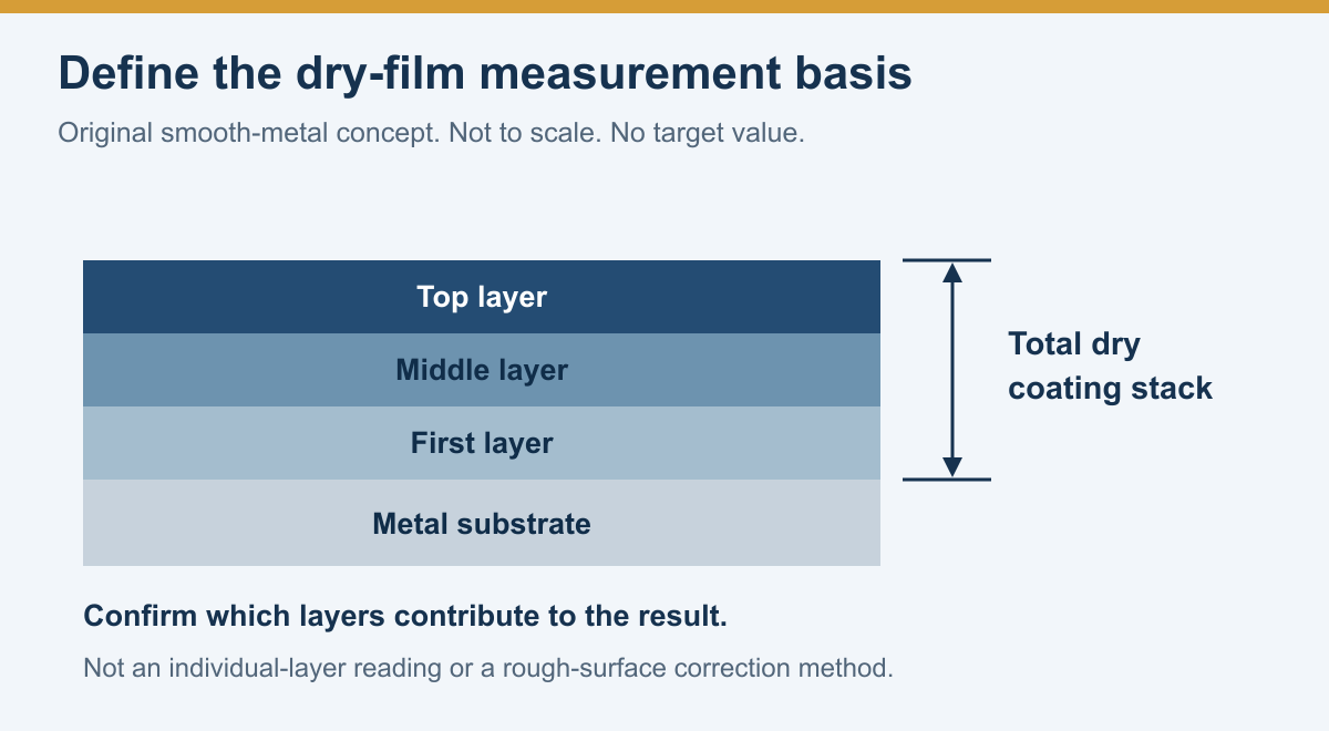
For a conventional magnetic or eddy-current setup, establish which coating stack contributes to the displayed result. Do not label a reading over several retained layers as the thickness of the latest coat without a validated method for that claim. DeFelsko's coating-thickness gage overview distinguishes probes and applications, including specialized measurements. Verify the exact model and mode rather than assuming every gage separates layers.
Agree the inspection basis before collecting data
Use the following editorial planning checklist to resolve missing instructions before production readings begin. It is a coordination aid, not a prescribed sampling standard.
| Decision | Confirm in the work pack | Record with the results |
|---|---|---|
| Inspection lot | Drawing, compartment or hull-zone boundaries | Lot ID and location map revision |
| Coating stage | Which products and layers are present | Product/layer identifiers and application record |
| Measurement method | Applicable standard, edition, procedure and probe | Document revision, gage model and probe ID |
| Surface basis | How substrate geometry and roughness are addressed | Adjustment/correction method and supporting record |
| Sampling | Required reading groups, locations and coverage | Actual locations, counts and any inaccessible areas |
| Acceptance | Applicable limits and decision authority | Criterion reference, exceptions and disposition |
Use explicit units in the form and instrument export. Micrometres, written as µm, and mils are different units; 1 mil equals 25.4 µm. Keep the original values and unit labels when transferring files. A spreadsheet column called only “thickness” leaves the reviewer to guess.
If instructions name a standard, confirm the edition and any contract modifications. Do not combine a sampling rule from one method with a correction or acceptance rule from another simply because the resulting report looks familiar.
Separate calibration, verification and adjustment
DeFelsko's explanation of calibration, verification and adjustment treats these as distinct activities. Calibration is a controlled documented process performed by the manufacturer, its authorized agent or an appropriately accredited laboratory. Verification checks operation against suitable known references. Adjustment aligns the instrument with the particular measurement application according to its instructions.
For the job record, link the gage and probe identifiers to the relevant calibration evidence, verification results and adjustment record. A calibration certificate alone does not show that the instrument remained fit for use throughout today's inspection. If a verification fails, identify the affected measurements and follow the agreed review procedure before relying on them.
Ask practical handover questions: Can another inspector identify the reference used? Is its value and unit clear? Is the check result retained? Can the adjustment be traced to the substrate or representative test surface? These questions make a report reviewable without turning an on-site check into a claim of laboratory calibration.
Address roughness, geometry and access deliberately
DeFelsko's dry-film measurement guidance, originally published in 2016, describes influences including surface profile, curvature, substrate properties and thin metal. Its practical message remains relevant: use the instrument instructions and the agreed measurement basis for the actual surface.
On blast-cleaned steel, document how the approved method handles profile. Do not subtract a convenient profile value from every result or apply a second correction after one is already built into the recorded measurement process. If the bare substrate is no longer available, resolve the permitted alternative before recording acceptance results.
A weld toe, narrow edge and broad flat plate may require different access or probe arrangements. Record restricted access rather than quietly substituting an easier nearby location. The separate surface-profile measurement guide explains the preparation-stage task; a profile result is not a dry-film reading.
Preserve readings and the decision trail
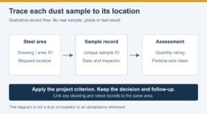
Build the report so a reviewer can follow a result back to its position and measurement setup. Keep the instrument export together with the location map. Explain corrections and authorized exclusions without replacing the original data.
The blank record below is an editorial template. Add the reading, spot or area fields required by the selected procedure; no universal grouping count is assigned here.
| Record group | Fields to complete | Supporting evidence |
|---|---|---|
| Job and lot | Vessel/project, area ID, drawing, inspection stage | Marked inspection map |
| Coating | Product, batch, layer sequence, application date | Application and batch records |
| Equipment | Gage/probe IDs, model, mode and units | Instrument and calibration references |
| Measurement basis | Procedure revision, surface adjustment/correction | Setup and verification records |
| Results | Location IDs, original readings, required group summaries | Instrument export or controlled field sheet |
| Decision | Criterion, exceptions, repair/retest IDs, release authority | Signed disposition and retest record |
Keep an accessible area with an unresolved result distinguishable from an area that could not be inspected. Both need an action, but they do not describe the same evidence gap.
Handle exceptions before releasing the area
Use the decision prompts below to organize a review. They do not authorize a repair or override the coating specification.
| Observation | Next check | Record before closure |
|---|---|---|
| Results conflict with the criterion | Confirm units, layer stage, setup and location identity | Verified basis and authorized disposition |
| Instrument check becomes unsatisfactory | Identify measurements since the last acceptable check | Affected lot, equipment action and required reinspection |
| Only part of the area is accessible | Review the approved inspection coverage | Uninspected locations and follow-up responsibility |
| An additional coat or repair is proposed | Obtain system-specific instructions and inspection requirements | Repair reference and linked retest results |
Averages should not conceal unresolved locations where the procedure requires separate decisions. Retain the reason for a hold and the evidence that closed it. A thickness report also does not establish adhesion, absence of holidays or readiness for immersion; those checks remain separate requirements where specified.
Confirm JD product and system requirements
The current public JD marine epoxy primer page links product information, including the JDH815 sheet. That sheet lists a nominal dry-film value for the product. It does not provide a complete project sampling plan, measurement-adjustment procedure or acceptance rule for every layer and completed system. Its controlled latest revision and component SDS should be confirmed for the actual job.
No JD thickness limit or generic percentage tolerance is assigned in this guide. Request the applicable coating schedule and approved inspection requirements. For application control before drying, see the separate wet-film thickness calculation guide; the calculated wet target does not replace dry-film inspection.
Frequently asked questions
Does one acceptable reading release a coated area?
Only the agreed sampling and acceptance procedure can establish the required evidence. Keep location coverage and any required grouped results in the report.
Can I use the same correction on every surface?
Confirm applicability to the actual substrate, preparation and probe setup. Record the approved basis and resolve changed conditions before using it elsewhere.
Does dry-film thickness prove that the coating has fully cured?
Thickness and cure are separate inspection questions. Use the product-specific curing and service-release requirements alongside the thickness record.
Request a coating inspection document review
Planning a dry-dock handover or reviewing a contractor's DFT report? Contact JD Marine Paint with the substrate, service area, exact product/layer schedule, proposed method, unit-labeled readings and inspection map. Include the applicable specification and unresolved locations so the review starts with the relevant coating and location evidence.