What should you do when marine paint starts to sag?
Paint sagging is localized downward movement of a coating film, often visible as runs, curtains or a heavier ridge below the original application area. Pause work in the affected area, identify the coating and application conditions, and obtain a system-specific correction plan before recoating. The shape is an observation; it does not establish the cause, remaining film thickness or an acceptable repair.
For a shipyard supervisor handing over a vertical hull section, the useful question is: what changed between the application record and the affected location? A marked area, batch reference and time-stamped observations give the technical reviewer a better starting point than an unlocated close-up. Keep investigation, repair authorization and final inspection connected to the same area ID.
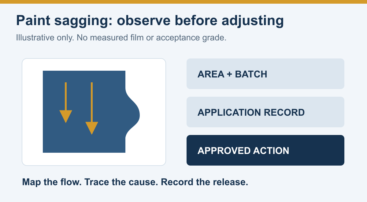
Original educational diagram, not a project photograph or defect acceptance reference. The coating shape and arrows are illustrative; they do not identify a cause or prescribe a repair.
Map the observation before changing the process
Record where the flow begins and ends, whether it follows an overlap or weld, and whether similar marks occur elsewhere in the application sequence. Include a wider photograph showing the location and a close view with a suitable size reference. Identify when each photograph was taken relative to application. A photograph alone cannot establish cure, thickness or adhesion.
Use factual wording such as “downward ridge on vertical panel at the second-pass overlap.” Keep a proposed explanation in a separate field. This prevents “too much thinner” from becoming the recorded cause before the batch and thinning records have been checked.
The following is an original investigation worksheet. It sets no JD product limits or inspection frequency.
| Record group | Capture at the affected location | Keep with the record |
|---|---|---|
| Area and layer | Vessel/structure, marked zone, orientation, product and layer sequence | Location sketch and photograph IDs |
| Material | Component names, batch numbers, mixing time and any addition | Batch sheet and approved material instructions |
| Application | Method, equipment ID, tip/nozzle identification and recorded settings | Equipment instructions and application log |
| Conditions | Air, substrate and material temperature; humidity and other required conditions | Time, units, instrument ID and measurement position |
| Film evidence | Available wet-film observations and later dry-film results, separately identified | Measurement stage, location and applicable procedure |
| Timing | Start/finish, when flow was first noticed and subsequent work nearby | Time zone and linked shift/handover record |
Use explicit units: for example, temperature in °C or °F, film thickness in µm or mils, and pressure in the unit actually used by the equipment. Do not combine pressure readings from different points in a spray system without identifying the measurement location.
Investigate plausible contributors with evidence
Review material temperature and thinning together
Hempel's hot-climate application guideline describes a relationship between warmer paint, lower viscosity and a greater tendency to sag; it also identifies thinning as a possible contributor. This is general guidance for Hempel products, not an instruction to alter a JD coating or a way to diagnose one from appearance.
Compare the actual material temperature and documented additions with the applicable JD instructions. If a viscosity result is available, retain its method and temperature. The separate marine paint viscosity guide explains why an unlabeled flow time is not a transferable material specification.
Review delivery and technique for the equipment in use
Graco's air-assisted spray troubleshooting guide lists fluid delivery, tip condition/selection and technique among possible contributors to runs. Its equipment context matters: an air-assisted guide is not a pressure-setting chart for every airless sprayer, brush or roller operation.
For the actual setup, review the relevant equipment instructions and coating application requirements together. Do not copy a setting from a different gun or assume that changing one control produces a predictable result on another system.
| Observed pattern or record gap | Question to investigate | Evidence needed before an adjustment |
|---|---|---|
| Flow concentrated at overlaps | Was material deposited differently there? | Pass sequence, local film observations and technique review |
| Repeated runs with one spray setup | Do tip condition and delivery match the approved setup? | Equipment identification, inspection and recorded settings |
| Flow noticed after a change in material conditions | Did temperature or an addition change? | Material temperature, batch log and addition identity/amount |
| No reliable wet-film record | What can still be established at this stage? | A permitted inspection plan; no reconstructed measurement |
| Similar marks across different batches | Is there a shared process or location factor? | Area-by-area comparison, with unresolved alternatives retained |
These are review prompts, not proof of causation. More than one contributor may be present. Record an explanation as confirmed only when the evidence and responsible technical review support it.
Separate a controlled trial from repair of existing film
Before restarting work, agree who can authorize a trial, which variable is being examined and how the result will be judged. Use the specified coating, suitable representative conditions and the applicable equipment procedure. Retain the original settings and the changed settings so that the comparison remains understandable.
A trial should answer a defined question, such as whether an approved delivery adjustment changes the local film distribution. It does not retroactively accept the sagged area. Keep the trial location and its inspection results separate from the defect and repair records.
If the current product instructions, thinner identity, allowed addition or equipment suitability cannot be established, retain the affected work on hold for technical clarification. Adding solvent by eye or altering component proportions is not a documented correction plan. Equipment intervention must follow its safety instructions, including the applicable pressure-relief procedure.
Repair and reinspection need their own release record
Do not use a generic “sand and overcoat” response for every coating. Establish the film condition, intended service and manufacturer-approved treatment first. The plan needs to address the material retained, any material removed, the preparation of the repair boundary and the replacement coating sequence.
| Review stage | Resolve for this repair | Close-out evidence |
|---|---|---|
| Disposition | Required treatment and authority to proceed | Referenced technical instruction for the identified area |
| Preparation | Suitable condition for working the film; retained coating and repair boundary | Preparation record and required checks |
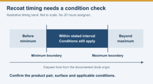
| Replacement coat | Product sequence, application requirements and timing | Batch/application records and approved timing basis |
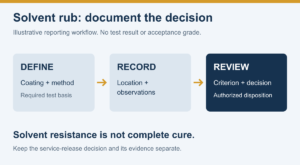
| Reinspection | Required appearance, thickness and other specified checks | Location-linked results, exceptions and signed decision |
For application control, use the wet-film thickness planning guide where applicable. After drying, the dry-film inspection guide covers the separate measurement record. A smooth-looking repair does not establish that the required film build has been restored.
If preparation or additional coating changes the schedule, confirm the recoat window for the actual product pair and conditions. Completion of a cosmetic correction does not, by itself, release a tank or hull area for its intended service.
Confirm the JD product documents before choosing an adjustment
Start with the exact product in the JD marine epoxy primer range and its controlled application documents. The available JDH815 public sheet identifies application methods and a thinner, but does not provide a complete sag-repair procedure or a universal thinning allowance.
Ask for the current TDS, relevant component/thinner SDS and system-specific technical instructions for the job. This guide assigns no JD pressure, nozzle size, temperature limit, solvent percentage, drying period or permitted sag size.
Frequently asked questions
Does sagging prove that too much thinner was used?
No. It is one possible explanation to examine alongside the material conditions, delivery, technique and local deposition records. Confirm the cause through evidence rather than recording a visual assumption as a batch error.
Can an acceptable average thickness close the defect?
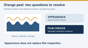
Use the specified inspection and acceptance procedure. Preserve the locations associated with the flow and repair; an overall average should not erase an unresolved local condition. Appearance and film thickness answer different inspection questions.
Should the applicator correct a sag while the film is still wet?
Only a product- and situation-appropriate approved procedure can establish whether and how that intervention is suitable. Identify the film condition and obtain the required instructions; this article provides no universal wet-film repair method.
Send a traceable sagging inquiry
Reviewing runs on a vertical hull section or a tank bulkhead? Contact JD Marine Paint with the product/layer, service area, location photographs, batch and addition records, condition readings and available film measurements. Include the proposed next operation and any missing documents so the technical review can address both the affected film and the restart plan.