Surface profile measurement checks the roughness created by surface preparation against the requirement for the selected coating system. For blast-cleaned marine steel, identify the required parameter, measurement method, units and acceptance rule before taking readings. A visual cleanliness grade or a soluble-salt result does not establish the surface profile, and a profile reading alone does not release steel for painting.
For shipyard inspectors, blasting supervisors and primer specifiers, the useful outcome is a traceable measurement record tied to the actual work area and coating specification. This guide explains how to organize that decision; the complete adopted procedure governs field testing.
Separate profile from cleanliness and coating thickness
Blast-cleaned steel has peaks and valleys. Their geometry is a different characteristic from visible rust cleanliness, chemical contamination and the thickness of a subsequently applied film.
ASTM D4417 describes field measurement of blast-cleaned surface profile. Its public scope identifies the coating manufacturer's requirement or job specification as the relevant basis for checking the prepared surface. It does not supply one target that every marine primer needs.
Keep these checks separate in the inspection plan:
- Visual condition: the specified cleanliness assessment and any relevant preparation defects.
- Contamination: the required dust, oil, salt and other checks. See the separate soluble salt testing guide.
- Surface profile: the specified parameter and method, with the required distribution of readings.
- Film thickness: the coating thickness requirement and its own measurement procedure after application.
Do not use an Sa 2½ description as a numerical profile result. Likewise, a roughness reading is not a measurement of how much paint has been applied.
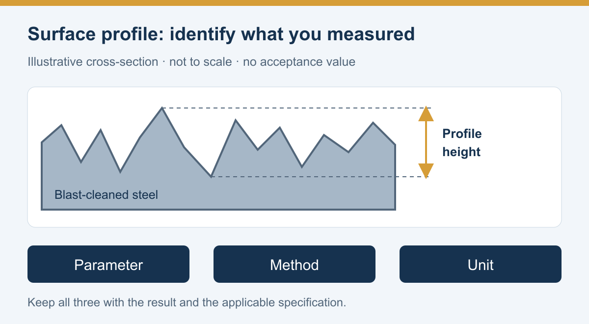
Original schematic, not to scale. It shows geometry only, not a measured result, acceptance range or sampling rule.
Choose the method required by the specification
Common field approaches include comparison against reference surfaces, depth-micrometer readings and replica-tape measurement. DeFelsko's surface-profile instrument overview explains their different measurement principles. The following table is a selection aid, not permission to substitute one method for another.
| Approach | What it does | What to establish before using the result |
|---|---|---|
| Profile comparator | Compares the prepared surface with reference segments by the specified visual/tactile procedure | Comparator type, abrasive relevance, condition, grading system and required method |
| Depth micrometer | Uses a supporting foot and pointed probe to assess local peak-to-valley geometry | Suitable probe and contact geometry, verification, reading locations and reporting rule |
| Replica tape with a suitable gauge | Forms an impression that is measured and interpreted under the specified tape procedure | Tape grade/range, impression quality, gauge settings, corrections and sample identity |
Replica tape has its own scope. ISO 8503-5:2017 describes a field method for abrasive-blast-cleaned surfaces, applicable within the profile-height range of the tape grade being used. That is a measurement-range condition, not a coating's acceptable profile range.
Standards check, 2 November 2026: ASTM's indexed official catalog lists D4417-21 as active. ISO lists 8503-5:2017 as published, with a draft replacement under development. Confirm the contract's adopted edition and current catalog status before testing; do not treat draft text or an older comparison article as the governing procedure.
Define the parameter and units before collecting data
“Roughness” without a parameter is incomplete. A comparator grade, a peak-to-valley profile-height result and another roughness parameter do not become interchangeable simply because they describe the same steel.
DeFelsko's comparison of measurement methods, updated in September 2021, illustrates why measurement principles and data treatment affect the reported result. Use it as background, rather than adopting its study's sampling or averaging approach as a current project instruction.
Write the required parameter, method/edition, units, acceptance range and calculation or grading rule into the inspection plan. If an instrument offers several analysis modes, record which one was used. Do not relabel a general Ra result as the specified peak-to-valley profile height, or replace a required comparator grade with an unrelated numerical average.
Convert units without changing the measurement basis
1 mil = 25.4 µm. Here, a mil means one thousandth of an inch, not a millimeter.
For a unit exercise only, 2.0 mil × 25.4 = 50.8 µm. These quantities are illustrative, not a recommended profile or a site result. This arithmetic preserves the same parameter and method; it cannot convert one measurement principle into another. Retain sensible precision consistent with the original instrument and report.
Verify the instrument and the measurement setup
Check the instrument's identity, suitable range and condition, then follow its current verification instructions. Distinguish a field accuracy check from the manufacturer's calibration process.
For example, the PosiTector SPG instruction manual describes verification using a clean glass zero plate and a check shim. It also calls for stable probe contact and lifting the probe between readings. Those instructions belong to that instrument; another gauge may require a different setup.
Make the measurement location suitable for the selected method. Loose debris, unstable contact, an unsuitable tape grade or poor impression can undermine the result. Review curved surfaces, restricted access and edges with the responsible inspector rather than assuming the flat-surface arrangement applies everywhere. Record an invalid attempt and its reason instead of silently treating it as valid data.
Map readings and apply the agreed acceptance rule
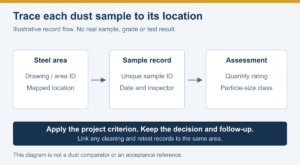
Identify areas on a drawing or location map before inspection. The approved plan should define the number and distribution of locations, readings per location, reporting calculation and response to a nonconforming area. This article supplies none of those as universal numerical rules.
Preserve individual readings and location identifiers as required. A single attractive number or an unexplained average can conceal variation. Conversely, do not discard inconvenient readings or invent a new maximum-based calculation to obtain acceptance.
| Finding | Review before release | Record the outcome |
|---|---|---|
| Required parameter or method is missing | Resolve the specification/report mismatch | Agreed requirement and responsible reviewer |
| Gauge or sample validity is uncertain | Follow the approved verification and repeat-measurement procedure | Original attempt, issue, corrective action and repeat IDs |
| Results fall outside the specified criterion | Identify the affected area and obtain approved disposition | Area boundary, preparation action and reinspection record |
| Profile is acceptable but other checks remain open | Complete the separate cleanliness and environmental hold points | Outstanding checks and final release authority |
Do not assume that extra primer compensates for an unacceptable profile. Preparation changes, coating-system changes or additional film build require the applicable technical approval.
Keep a usable surface-profile inspection record
This blank template is an editorial inspection aid. It contains no measured project results or approved acceptance values.
| Record field | Information to enter |
|---|---|
| Work area | Vessel/project, compartment or structure, drawing reference and mapped location ID |
| Surface condition | Substrate, preparation method, abrasive information where required and inspection stage |
| Requirement | Specification clause, parameter, units, accepted method/edition and criterion |
| Equipment | Instrument/probe or comparator ID, tape grade/lot if applicable, verification evidence and settings |
| Measurements | Original readings or grades, sample IDs, locations and procedure-required calculation |
| Validity | Contact/impression observations, exclusions with reasons and repeat-measurement references |
| Disposition | Acceptance decision, affected area, approved corrective action, reinspection and release signature/date |
Retain gauge exports and labeled tape samples where the procedure requires them. Keep photographs linked to the location map; a photograph of rough steel does not replace a measured profile record.
Connect the result to the selected marine primer
The public JD marine epoxy primer preparation guide, revision 2026.07, directs preparation to the project specification and final requirements to current product documentation. The reviewed public JD documents do not establish a universal profile range or a roughness-to-DFT ratio for the primer range.
Use the marine epoxy primer category to identify candidate products, then obtain the current product-specific TDS, component SDS and approved system requirements. Controlled current documents must be confirmed for the actual work; the public planning summary does not replace them.
For the broader workflow, refer to dry-docking surface treatment and the marine primer application and troubleshooting guide. Keep the profile record as one distinct preparation hold point.
Frequently asked questions
Is a profile reading the same as a dry-film-thickness reading?
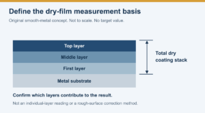
No. They describe different characteristics and require the appropriate instrument and procedure. Do not report a coating-thickness gauge value as a surface-profile result.
Can I replace replica tape with a depth micrometer?
Only when the adopted specification and responsible authority permit the method. Resolve the required parameter, reporting rule and applicability before substituting equipment.
What is the correct profile for every marine epoxy primer?
There is no universal value in this guide. Use the selected product's current requirements and project specification, with the named measurement method and units.
Request a primer and surface-preparation review
Send JD Marine Paint your project details: substrate and preparation method, proposed primer/system, specified profile parameter and range, instrument method, readings with units and the location record. Include relevant cleanliness results so the technical inquiry can address the complete pre-coating condition.